By Carl Sechen
From my B.E.E measure on the collage of Minnesota and throughout my S.M. measure at M.I.T., I had really good in sturdy country units and microelectronics. I made the choice to change to computer-aided layout (CAD) in 1981, just a 12 months or so sooner than the creation of the simulated annealing set of rules by way of Scott Kirkpatrick, Dan Gelatt, and Mario Vecchi of the IBM Thomas 1. Watson examine heart. simply because Prof. Alberto Sangiovanni-Vincentelli, my UC Berkeley consultant, have been a expert at IBM, I re ceived a duplicate of the unique IBM inner file on simulated annealing nearly the day of its unlock. Given my history in statistical mechanics and sturdy country physics, i used to be instantly inspired by way of this new combinatorial optimization process. As Prof. Sangiovanni-Vincentelli had prompt I paintings within the components of placement and routing, it was once in those geographical regions that I sought to discover this new set of rules. My flJ'St implementation of simulated annealing was once for an island-style gate array placement challenge. This paintings is gifted within the Appendix of this e-book. i used to be relatively struck by means of the impact of a nonzero temperature on what differently seems to be a random in terchange algorithm.
Read or Download VLSI Placement and Global Routing Using Simulated Annealing PDF
Best design books
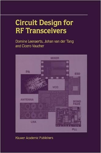
Circuit Design for RF Transceivers
Circuit layout for RF Transceivers covers key development blocks that are had to make an built-in transceiver for instant and mobile functions, that's low-noise amplifiers, mixers, voltage managed oscillators, RF strength amplifiers and phase-locked loop structures. ranging from particular RF suggestions and requisites, the authors talk about the circuits intimately and supply suggestions to many layout difficulties.
So much designers be aware of that yellow textual content offered opposed to a blue heritage reads sincerely and simply, yet what number can clarify why, and what particularly are the simplest how one can aid others and ourselves basically see key styles in a host of knowledge? This e-book explores the paintings and technological know-how of why we see gadgets the best way we do.
Computer Principles and Design in Verilog HDL
Makes use of Verilog HDL to demonstrate computing device structure and microprocessor layout, permitting readers to without difficulty simulate and modify the operation of every layout, and therefore construct industrially suitable talents- Introduces the pc rules, desktop layout, and the way to exploit Verilog HDL (Hardware Description Language) to enforce the layout- offers the talents for designing processor/arithmetic/cpu chips, together with the original software of Verilog HDL fabric for CPU (central processing unit) implementation- regardless of the numerous books on Verilog and machine structure and microprocessor layout, few, if any, use Verilog as a key software in supporting a pupil to appreciate those layout ideas- A spouse site contains colour figures, Verilog HDL codes, additional attempt benches now not present in the e-book, and PDFs of the figures and simulation waveforms for teachers
- Thermoelectric Nanomaterials: Materials Design and Applications
- Geometric Design Tolerancing: Theories, Standards and Applications
- Aircraft Conceptual Design Synthesis (PB)
- Voice: User Interface Design by Michael H. Cohen (2004-02-02)
- Flight Control Systems: Practical Issues in Design and Implementation (I E E Control Engineering Series) [Hardcover] [2000] (Author) Roger W. Pratt
- Circuit and Interconnect Design for RF and High Bit-Rate Applications
Extra resources for VLSI Placement and Global Routing Using Simulated Annealing
Example text
And Z). The placement and routing model for gate array. as well as other row-based images. 6. Essentially. the cells are indicated as rectangles of common heights and various widths. and are arranged in rows. The terminal or pin positions are indicated as points within the cell bOWldary. Most often. these points are located on the boundary of the cell. The pins are given a label which is the name of the signal or net to which the pin belongs. A set of pins having the same label must be electrically interconnected Gate arrays shorten and simplify the design process.
In practice, A is limited to a maximum value thereby implying that the original cell a is not moved if a reduction in total routing length could not be found in A steps. If no cell exists which can be moved with A steps, the placement is said to be A-optimum. The results yielded by this method seemed to be comparable to those given by force-directed pairwise relaxation, for nominal values of £ and A. 3 = = I M. Hanan, P. Wolff, and B. Agule, "Some Experimental Results on Plaoement Techniquel," (1976).
On the other hand, the degree of difficulty in tenns of fabrication is strongly related to the number of metal layers. 1 w. DeCamp, O. Sporzynski, and H. Burbank, "Oate Array and Standard Cell Approach," (1986). 6 I. -____ celiA B I I I roLw~1 I row 4 C :. I I__. ___ .... 3 A row-based gate array layout image. Since every chip contains the same pattern of transistors, regardless of its fWlction, the chips can be manufactured in volume. The metal personality is added only on demand for a particular fWlction.


