By R. A. DeCarlo and P. Lin
Read or Download Linear circuit analysis - solution manuel PDF
Similar design books
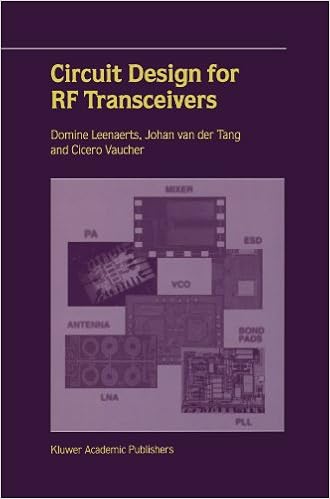
Circuit Design for RF Transceivers
Circuit layout for RF Transceivers covers key development blocks that are had to make an built-in transceiver for instant and mobile functions, that's low-noise amplifiers, mixers, voltage managed oscillators, RF strength amplifiers and phase-locked loop structures. ranging from particular RF ideas and standards, the authors talk about the circuits intimately and supply suggestions to many layout difficulties.
Such a lot designers understand that yellow textual content awarded opposed to a blue history reads essentially and simply, yet what number can clarify why, and what rather are the easiest how one can aid others and ourselves essentially see key styles in a number of information? This ebook explores the artwork and technology of why we see gadgets the way in which we do.
Computer Principles and Design in Verilog HDL
Makes use of Verilog HDL to demonstrate desktop structure and microprocessor layout, permitting readers to effectively simulate and regulate the operation of every layout, and hence construct industrially correct abilities- Introduces the pc ideas, laptop layout, and the way to take advantage of Verilog HDL (Hardware Description Language) to enforce the layout- presents the abilities for designing processor/arithmetic/cpu chips, together with the original software of Verilog HDL fabric for CPU (central processing unit) implementation- regardless of the numerous books on Verilog and laptop structure and microprocessor layout, few, if any, use Verilog as a key software in supporting a pupil to appreciate those layout innovations- A better half web site contains colour figures, Verilog HDL codes, additional try benches now not present in the booklet, and PDFs of the figures and simulation waveforms for teachers
- The Theology of Craft and the Craft of Work: From Tabernacle to Eucharist
- Process Engineering Economics, 1st Edition
- God, Evil and Design: An Introduction to the Philosophical Issues
- Grain Boundary Controlled Properties of Fine Ceramics: JFCC Workshop Series: Materials Processing and Design
- The non-designer's Indesign book : essential design techniques for print projects
- Writing About Architecture: Mastering the Language of Buildings and Cities (Architecture Briefs)
Additional resources for Linear circuit analysis - solution manuel
Sample text
69. C20 = 50 Ah (a) In eq. 2A (b) Calculate the capacity for n=10 and T=10, this yields 42 Ah. 70. 278W . (b) Following is the graph, and the script used to generate it. *" which means that the division %is performed for each value of RL. *IL); xlabel('Resistance in Ohms'); ylabel('Current in mA'); %The use of subplot lets you subdivide the graphing %window in two halfs. 71. 72. 6e3; © R. A. DeCarlo, P. M. Lin Chap 2 Probs P2 - 17 © R. A. DeCarlo, P. M. 73. 73 R1=20; R2=40; R3=60; R4=30; R5=10; R6=135; R7=150; R8=300; R9=130; R10=200; R11=50; Ga=1/R10+1/R11; Ra=1/Ga; Rb=Ra+R9+(1/(1/R7+1/R8)); c b a R4 R6 R7 R9 Chap 2 Probs P2 - 18 © R.
7566W 20 20 (d) In this part, we take the above matrix equation and solve it for each value of Gs. t. changes in Gs. The following plot is the voltage difference between the two nodes as a function of Gs, and hence as a function of temperature. As can be seen, in this figure, the voltage difference between B and C does not change linearly with Rs. Since this resistance itself changes linearly with temperature, this means that VB-VC does not change proportionally to temperature. 6. 33W. 12 We are required to write the equations in matrix form.
A. DeCarlo, P. M. Lin Chap 2 Probs P2 - 17 © R. A. DeCarlo, P. M. 73. 73 R1=20; R2=40; R3=60; R4=30; R5=10; R6=135; R7=150; R8=300; R9=130; R10=200; R11=50; Ga=1/R10+1/R11; Ra=1/Ga; Rb=Ra+R9+(1/(1/R7+1/R8)); c b a R4 R6 R7 R9 Chap 2 Probs P2 - 18 © R. A. DeCarlo, P. M. 74. 8mA PROBLEM SOLUTIONS CHAPTER 3. 1. 4 (a) It is evident from the figure that Vc = 20. We need to write two equations in Va and Vb and put them in matrix form. In this case, we can write the matrix equation by inspection. Note that the resistors are identified by conductance values.


