By Anindya Dasgupta, Parthasarathi Sensarma
This booklet describes goal purposes for synchronous structures: regulated 3-phase voltage offer and voltage sag mitigation. It offers an in depth layout method for converter switches and filters contemplating all steady-state, commutation and dynamic standards. This paintings has developed from formerly released study by means of the authors, which in flip is a part of a bigger attempt to extend the applying area of matrix converters to strength structures. The targets of the paintings were classified into the subsequent: constructing a dynamic version that gives enough layout insights; designing filters; and devising a keep watch over scheme. The low frequency dynamic version is first analyzed for regulated voltage offers assuming balanced method. The approach is modeled relative to a synchronous rotating (dq) body linearized round an working element. The input–output variables are comparable by way of non-diagonal move functionality matrices. person move functionality sub-matrices are sequentially investigated and it's proven that, looking on the enter strength, enter voltage and clear out parameters, the looks of a collection of correct part zeros is possible. The booklet then considers filter out layout, in addition to basic matters like ripple attenuation, rules, reactive present loading, and clear out losses. The e-book additionally addresses extra constraints which may be imposed via dynamic requisites and commutation. within the 3rd degree, voltage controller layout is distinctive for a 3-phase regulated voltage offer. In dq area, output voltage regulate represents a multivariable keep watch over challenge. this can be diminished to a unmarried variable keep watch over challenge whereas maintaining all attainable correct part zeros, thereby protecting the interior balance of the method. hence, the traditional unmarried variable keep an eye on layout method has been used to layout a controller. The analytically estimated dynamic reaction has been tested by way of experimental effects. It was once attainable to function the process past the serious energy boundary the place the precise part zeros emerge. finally, the built keep an eye on technique has been prolonged to voltage sag mitigation with enough transformations. A 3-wire linear load and both symmetrical and asymmetrical voltage sags were thought of. Experimentally got reaction time for sag mitigation used to be stumbled on to be under the ability provide holdup time of lots of the delicate equipment. This publication might be invaluable to either researchers and graduate scholars.
Read Online or Download Design and Control of Matrix Converters. Regulated 3-Phase Power Supply and Voltage Sag Mitigation for Linear Loads PDF
Best design books
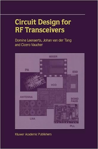
Circuit Design for RF Transceivers
Circuit layout for RF Transceivers covers key development blocks that are had to make an built-in transceiver for instant and mobile purposes, that's low-noise amplifiers, mixers, voltage managed oscillators, RF strength amplifiers and phase-locked loop structures. ranging from targeted RF suggestions and standards, the authors speak about the circuits intimately and supply options to many layout difficulties.
Such a lot designers recognize that yellow textual content awarded opposed to a blue historical past reads in actual fact and simply, yet what number can clarify why, and what relatively are the easiest how you can support others and ourselves sincerely see key styles in a number of information? This e-book explores the paintings and technology of why we see items the way in which we do.
Computer Principles and Design in Verilog HDL
Makes use of Verilog HDL to demonstrate computing device structure and microprocessor layout, permitting readers to easily simulate and regulate the operation of every layout, and hence construct industrially appropriate abilities- Introduces the pc rules, desktop layout, and the way to take advantage of Verilog HDL (Hardware Description Language) to enforce the layout- offers the talents for designing processor/arithmetic/cpu chips, together with the original software of Verilog HDL fabric for CPU (central processing unit) implementation- regardless of the numerous books on Verilog and computing device structure and microprocessor layout, few, if any, use Verilog as a key instrument in aiding a pupil to appreciate those layout ideas- A better half site comprises colour figures, Verilog HDL codes, additional attempt benches no longer present in the e-book, and PDFs of the figures and simulation waveforms for teachers
- Basic design; principles and practice, Edition: [1st ed
- Architectural Drawing (Portfolio Skills: Architecture)
- The Innovation Paradigm Replaced - Creative New Product Design
- Yagi antenna design
Extra info for Design and Control of Matrix Converters. Regulated 3-Phase Power Supply and Voltage Sag Mitigation for Linear Loads
Sample text
18), the input phase to output line voltage low frequency gain matrix is obtained as ⎡ ⎤⎡ ⎤T dα + dβ dμ + dγ mv {mi }T = ⎣ −dα ⎦ ⎣ −dμ ⎦ . 1 Low Frequency Gain of 3-Phase MC 33 ⎤ ⎡ ⎤⎡ ⎤T ⎡ ⎤ dα + dβ v AB dμ + dγ va ⎣ v BC ⎦ = ⎣ −dα ⎦ ⎣ −dμ ⎦ ⎣ vb ⎦ vC A −dβ −dγ vc ⎡ ⎡ ⎤ dμ (dα + dβ )(va − vb ) − dγ (dα + dβ )(vc − va ) ⎦ −dα dμ (va − vb ) + dα dγ (vc − va ) =⎣ −dβ dμ (va − vb ) + dβ dγ (vc − va ) ⎡ ⎡ ⎤ ⎤ dμ (dα + dβ ) −dγ (dα + dβ ) ⎦ vca . 29) Thus there are four combinations of duty cycles dα dμ , dα dγ , dβ dμ and dβ dγ corresponding to the active states Vα Iμ , Vα Iγ , Vβ Iμ and Vβ Iγ .
5 shows the SVs of the CSC construct. The duty cycles for the switches of the fictitious CSC part are determined in the same manner as their VSC counterparts. They are dμ = Iˆin Iˆin sin(60◦ − θ S I ) = m i sin(60◦ − θ S I ) & dγ = sin(θ S I ) = m i sin(θ S I ). 5 Input currents when I¯in is in sector I During d6 (dμ ) During d1 (dγ ) + – a b a c ia ib ic −→ Idc −Idc 0 −→ Idc 0 −Idc Fig. 5 Input current vectors I2 I3 III I0 IV I4 I1 II sector I VI V ωi t ϕc ϕ i = 0 I6 I5 ∗ Here, θ S I , μ, γ are analogous to θ SV , α, β in Fig.
14) and therefore the target input current rotating vector is ∗ I¯in = 2 ∗ (i + i b∗ e j2π/3 + i c∗ e− j2π/3 ) = 3 a 3 ˆ j (ωi t−ϕc −ϕi ) . 4. 5 shows the SVs of the CSC construct. The duty cycles for the switches of the fictitious CSC part are determined in the same manner as their VSC counterparts. They are dμ = Iˆin Iˆin sin(60◦ − θ S I ) = m i sin(60◦ − θ S I ) & dγ = sin(θ S I ) = m i sin(θ S I ). 5 Input currents when I¯in is in sector I During d6 (dμ ) During d1 (dγ ) + – a b a c ia ib ic −→ Idc −Idc 0 −→ Idc 0 −Idc Fig.


